1. BGP demo
The generated BGP demo loads automatically. It contains 13 routers, 22 BGP sessions, and two route reflectors with deliberately different BMP capabilities.
- Confirm that the generated demo topology is present; no upload or manual demo load is required.
- Open General View and confirm that the BGP overlay is visible. The overlay is enabled by default; the control can hide and restore it.
- Find the routers with Router IDs 123.123.100.100 (RFC 7854) and 123.123.101.101 (RFC 7854 + RFC 9069 + RFC 8671). These RFCs identify which RIBs Topolograph receives through BMP from each route reflector.
The IGP topology remains the base graph. The BGP overlay adds sessions without replacing OSPF connectivity.
2. BGP sessions
Use both representations: the table provides precise BGP-session filtering, while the graphical BGP-session overlay shows where the selected session sits in the topology.
- Open BGP Sessions and filter the peer ip column by 123.123.31.31.
- Confirm that 123.123.31.31 (PE31) has one BGP session, with 123.123.100.100 (RR1), and no BGP session with 123.123.101.101 (RR2).
- Return to General View and locate the same PE-to-123.123.100.100 (RR1) adjacency in the BGP overlay.
The filtered BGP Sessions table below makes the RFC 7854 limitation case concrete: 123.123.31.31 (PE31) has one observed session, to 123.123.100.100 (RR1).
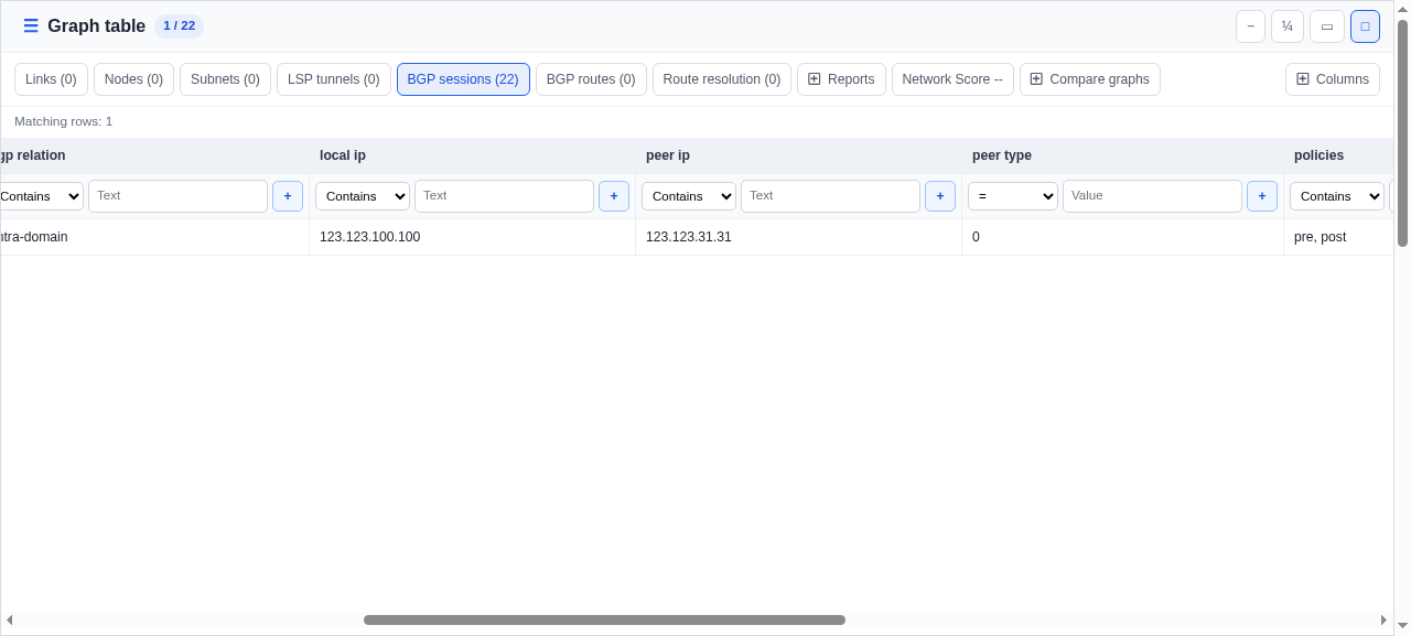
This 123.123.31.31 (PE31), with one BGP session, demonstrates the RFC 7854 limitation used later in the runbook.
3. RIB view
A BMP session established with a route reflector does not automatically provide a view of every RR client's table. A BMP session capable of exporting Loc-RIB provides the most accurate view of routing-table state. Topolograph can also work with explicit assumptions when some information is unavailable. For example, a device's RIB state can be inferred from a neighboring BMP speaker's RFC 8671 Adj-RIB-Out post-policy toward that device, even when no BMP session is established with the device itself.
BMP RFC coverage and path-calculation meaning
| BMP data | Owner and direction of the observed RIB | Can a path be calculated for the named device? | Required assumption |
|---|---|---|---|
| RFC 7854 pre-policy/post-policy Adj-RIB-In | Adj-RIB-In belongs to the BMP speaker and contains routes it received from a BGP neighbor | No | Adj-RIB-In does not show which route the BMP speaker selected and installed in Loc-RIB |
| RFC 9069 Loc-RIB | Loc-RIB belongs to the BMP speaker and contains its selected routes | Yes | None |
| RFC 8671 Adj-RIB-Out post-policy | Adj-RIB-Out belongs to the BMP speaker and contains routes it advertised to a specific BGP neighbor; for that neighbor, the feed is used as inferred Adj-RIB-In | Yes | The BGP neighbor's inbound policy and resulting Loc-RIB are not observed |
Routers in the demo network and routing-information visibility
| Router or group | BMP data available at Topolograph | Path calculation | Assumptions |
|---|---|---|---|
| 123.123.101.101 (RR2) | Loc-RIB belongs to 123.123.101.101 (RR2) and is received directly from it through RFC 9069 | Available | None |
| 123.123.30.30 (PE30); 123.14.14.14 (PE14) | Adj-RIB-Out post-policy belongs to 123.123.101.101 (RR2) and is directed to the corresponding device; for that device it is used as inferred Adj-RIB-In | Available | The device's inbound policy and resulting Loc-RIB are not observed |
| 123.10.10.10 (Core10); 123.123.110.110 (Core110) | Adj-RIB-Out post-policy belongs to 123.123.101.101 (RR2) and is directed to the corresponding device; for that device it is used as inferred Adj-RIB-In | Available | The device's inbound policy and resulting Loc-RIB are not observed |
| 123.15.15.15 (PE15) | The observed Loc-RIB belongs to 123.123.101.101 (RR2); its Adj-RIB-Out toward 123.15.15.15 (PE15) is not exported through BMP | Available | 123.123.101.101 (RR2) is assumed to advertise its selected route to 123.15.15.15 (PE15), and 123.15.15.15 (PE15) is assumed to accept it after inbound policy |
| 123.11.11.11 (Core11), 123.13.13.13 (Core13), 123.123.111.111 (Core111), 123.30.30.30 (Core30), 123.31.31.31 (Core31) | The observed Loc-RIB belongs to 123.123.101.101 (RR2); its Adj-RIB-Out toward these devices is not exported through BMP | Available | 123.123.101.101 (RR2) is assumed to advertise its selected route to each device, and each device is assumed to accept it after inbound policy |
| 123.123.100.100 (RR1) | RFC 7854 from 123.123.100.100 (RR1) shows its Adj-RIB-In, not its Loc-RIB; path calculation uses the Loc-RIB owned by 123.123.101.101 (RR2), whose Adj-RIB-Out toward RR1 is not exported through BMP | Available | 123.123.101.101 (RR2) is assumed to advertise its selected route to 123.123.100.100 (RR1), and 123.123.100.100 (RR1) is assumed to accept it after inbound policy |
| 123.123.31.31 (PE31) | Adj-RIB-In pre-policy and post-policy belongs to 123.123.100.100 (RR1) and contains routes it received from 123.123.31.31 (PE31); for PE31 this proves only its Adj-RIB-Out. No route data toward PE31 is available | Unavailable | The observed data shows neither the Loc-RIB nor Adj-RIB-In of 123.123.31.31 (PE31) |
123.123.101.101 (RR2) exports Adj-RIB-Out post-policy data through BMP only for selected BGP neighbors. This is valid: BMP Adj-RIB-Out monitoring is configured per BGP neighbor and address family, even though BGP itself maintains an Adj-RIB-Out for every established BGP neighbor.
4. BGP routes
Start from the graph-wide BGP Routes table before narrowing to one router. This is the place to inspect and filter the route data collected for the whole demo.
- Open Graph table and select BGP Routes. Leave the table in Live mode.
- Use prefix, bmp source, bmp ribs, peer ip, and path-attribute columns to find the route set you want to investigate.
The full-screen Live table below is the graph-wide BGP Routes view.
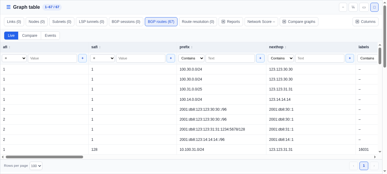
The BGP Routes table shows routes collected for the entire graph.
5. Route view in the device form
The route count in the device form shows the RIB view for that router: either its Loc-RIB received through a BMP session with the device, or Adj-RIB-Out post-policy received through a BMP session with a neighboring device.
- Click 123.14.14.14 (PE14) on the graph and find the BGP section in the device form.
- Confirm Routes is 4 and read the explanation: the routes were advertised by 123.123.101.101 (RR2) to this router through RFC 8671.
- Read the RIB breakdown. Adj-RIB-Out post-policy describes 123.123.101.101 (RR2)'s exported RIB; from 123.14.14.14 (PE14)'s perspective these four advertisements are its inferred Adj-RIB-In.
- The Adj-RIB-Out (post) 4 row is included in Routes: it is 123.123.101.101 (RR2)'s Adj-RIB-Out toward 123.14.14.14 (PE14), used as 123.14.14.14 (PE14)'s inferred Adj-RIB-In.
This form shows the RIB view for 123.14.14.14 (PE14): four routes from Adj-RIB-Out post-policy received through BMP from 123.123.101.101 (RR2).
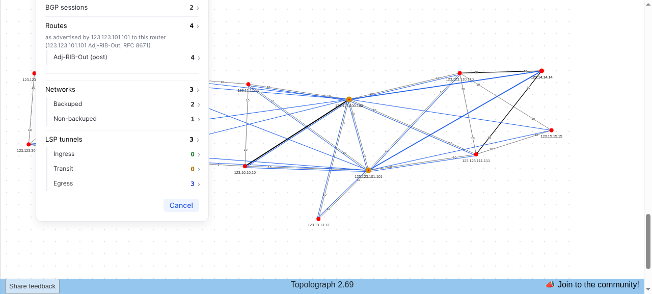
The device form for 123.14.14.14 (PE14) shows four routes, BMP source 123.123.101.101 (RR2), and RIB Adj-RIB-Out post-policy. Routes does not include routes that 123.14.14.14 (PE14) advertised to 123.123.101.101 (RR2) or other BMP observations not used for 123.14.14.14 (PE14)'s RIB view.
6. Filtering, sorting, and pagination for one node's routes
Open the route table from the device form; the table retains the RIB scope selected for 123.14.14.14 (PE14).
- Click Routes 4 on 123.14.14.14 (PE14). Confirm the drawer contains exactly 100.30.0.0/24, 10.100.31.0/24, 2001:db8:123:123:30:30::/96, and 2001:db8:100:31::/64.
- Filter prefix by 100.30.0.0/24. Matching rows and the table counter must both fall from 4 to 1.
- Clear the prefix filter and inspect other attributes independently: local pref = 250 leaves two VPN routes, afi = 2 leaves two IPv6 routes, and med = 20 leaves two routes from 123.123.30.30 (PE30).
- Clear filters and confirm all four 123.14.14.14 (PE14) routes return. Clearing a table filter must not remove the device scope established by the form.
- Click a sortable heading such as prefix, nexthop, local pref, or med. Repeated clicks cycle ascending, descending, and unsorted; address columns use address order, not text order.
- Use Rows per page for large route tables. The demo has only one page in this node-scoped example, so the previous and next controls correctly remain disabled.
The table below retains the 123.14.14.14 (PE14) scope and adds the prefix filter, leaving one matching route.
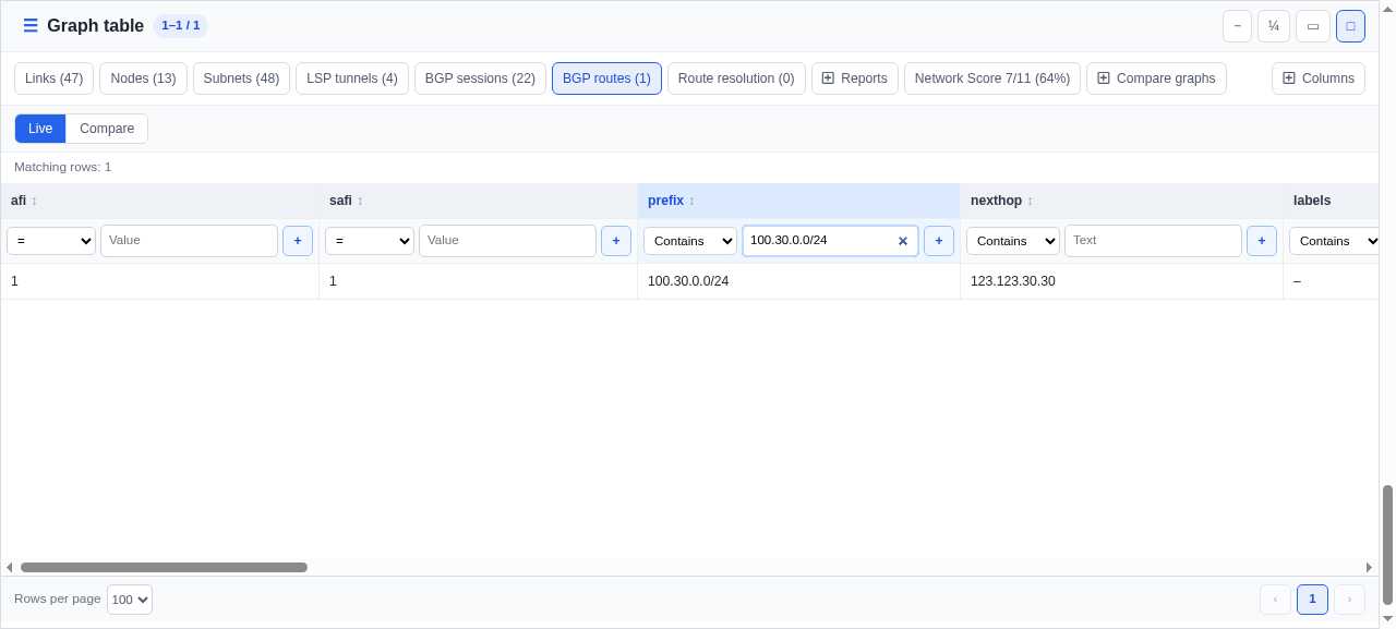
The filtered row shows 123.123.101.101 (RR2) as bmp source and Adj-RIB-Out post-policy as the observed RIB.
7. Best-path selection
For each prefix, the demo demonstrates one best-path selection criterion. Start with AS_PATH: compare the candidate attributes, then build the route from 123.123.101.101 (RR2) and verify the selected BGP next hop.
Pilot example: AS_PATH wins
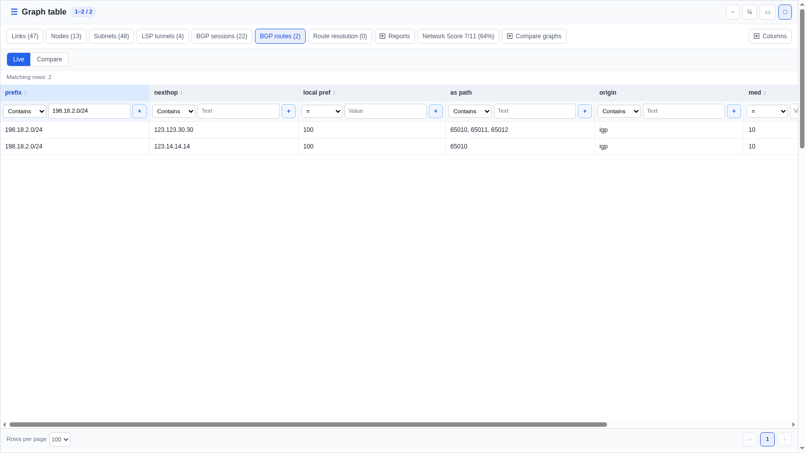
- Filter BGP Routes by 198.18.2.0/24.
- Compare the two candidates: both have
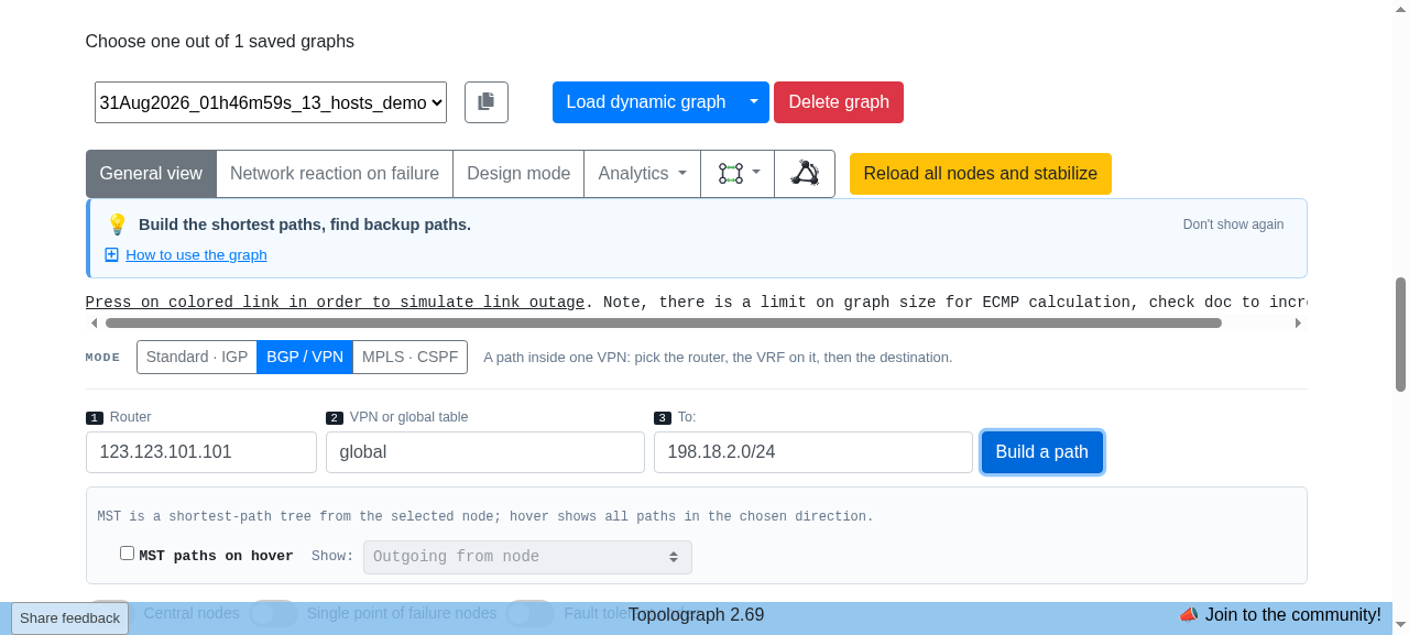
Local Preference100,OriginIGP, andMED10. 123.123.30.30 (PE30) advertisesAS_PATH65010 65011 65012; 123.14.14.14 (PE14) advertisesAS_PATH65010. - Switch to BGP / VPN path mode. Set Router to 123.123.101.101 (RR2), VPN or global table to global, and To to 198.18.2.0/24; then select Build a path.
- In Route resolution, confirm the first row is BGP on 123.123.101.101 (RR2) with next hop 123.14.14.14 (PE14). The remaining rows resolve that selected next hop through IGP.
Next, select the BGP / VPN path form and enter 123.123.101.101 (RR2), the global table, and this prefix.
In Route resolution, the first row shows 123.123.101.101 (RR2) selecting 123.14.14.14 (PE14) as the BGP next hop; the following rows are built from OSPF data.
The post-policy candidates differ in AS_PATH length while Local Preference, Origin, and MED tie. Building the route from 123.123.101.101 (RR2) selects 123.14.14.14 (PE14) as the BGP next hop; the following IGP rows show reachability to that BGP next hop.
Other best-path selection examples
| Decision | Prefix | Expected BGP next hop | What differs |
|---|---|---|---|
| LOCAL_PREF | 198.18.1.0/24 | 123.123.30.30 (PE30) | Higher Local Preference |
| AS_PATH | 198.18.2.0/24 | 123.14.14.14 (PE14) | Shorter AS_PATH |
| ORIGIN | 198.18.3.0/24 | 123.123.30.30 (PE30) | IGP origin beats incomplete |
| MED compared | 198.18.4.0/24 | 123.14.14.14 (PE14) | Lower MED from the same neighboring AS |
| MED not compared | 198.18.5.0/24 | 123.14.14.14 (PE14) | Different neighboring AS values make MED ineligible |
| Originator ID | 198.18.6.0/24 | 123.14.14.14 (PE14) | Lower originator ID after earlier ties |
Additional best-path selection criteria
The demo shows the six BGP best-path selection criteria listed in the table above. It does not demonstrate selection of eBGP over iBGP, IGP cost to the next hop, route age, cluster-list length, or BGP neighbor address.
8. Route-state comparison between two instants
Live shows the current route-table state. Compare evaluates route state at T0 and T1.
- Open the graph-wide BGP Routes table and switch from Live to Compare.
- Keep the default one-hour T0 to T1 window created when the demo loads, then press Run. The window also holds the MAC move from the EVPN section, so set the Prefix filter to Equals 100.14.210.0/24.
- The table shows one added route, 100.14.210.0/24; changed at contains the time of its last change before T1.
- added means the route is absent at T0 and present at T1; withdrawn means it is present at T0 and absent at T1; changed means it is present at both instants but its attributes differ. Events after T1 are outside the comparison.
- Switch back to Live to open the current route-table state.
The comparison below is the endpoint difference for the default demo window, not a chronological event log.
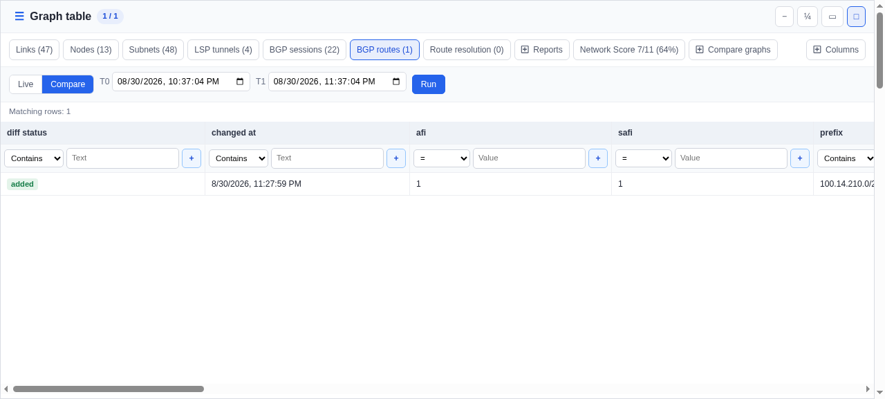
For the default demo interval, route 100.14.210.0/24 has status added and MED 80 at T1.
Individual BGP events
Events uses the same BGP Routes drawer and time range, but preserves every route and peer observation instead of reducing them to a T0-to-T1 difference.
- Switch from Compare to Events and keep a time window that covers the demo change burst. Press Clear filters first: the Prefix filter from Compare would hide the MAC move and the peer-down event.
- Press Run. The last three rows are one route add, one peer down event, and one route change for 100.14.210.0/24; the rows above them are the MAC move from the EVPN section.
- Use event, kind, prefix, peer source, peer target, and at to distinguish route changes from BGP-session state changes.
The Events view below lists the observations chronologically: the end of the MAC move, then the added route, the peer-down event, and the changed route with MED 80.
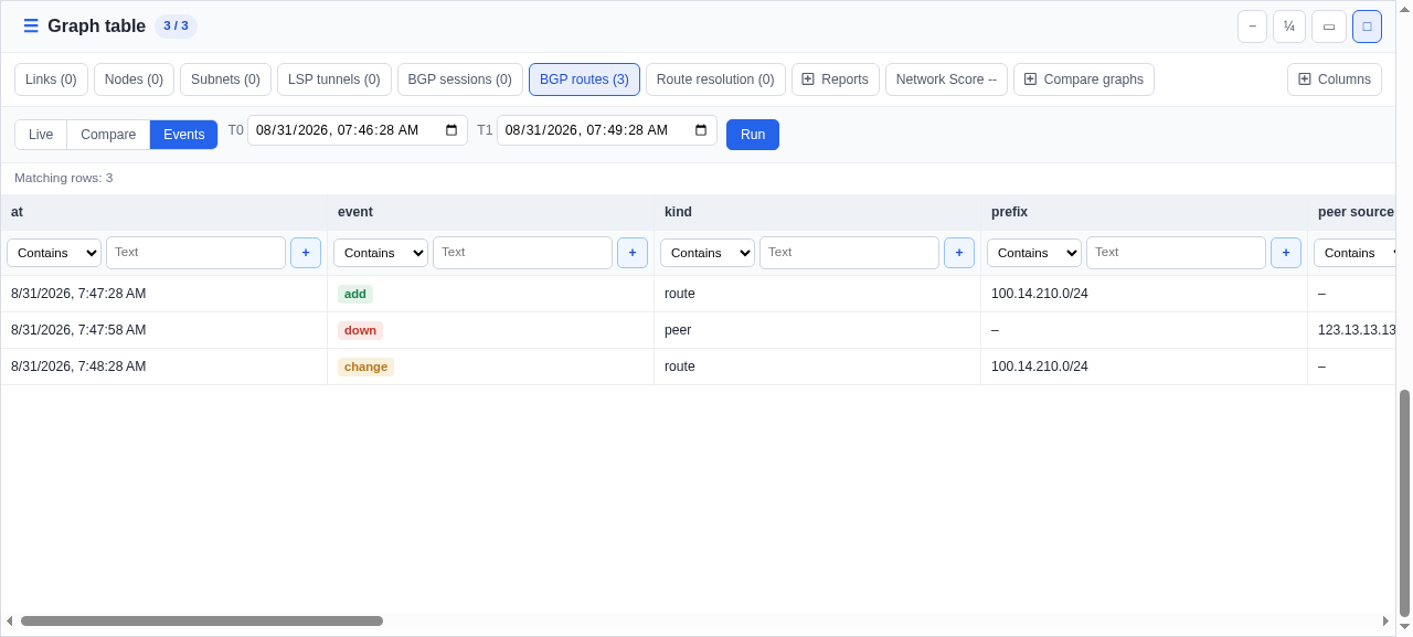
Events shows all three observations in order. Unlike Compare, it keeps intermediate events even when the final route state is unchanged.
9. BGP next-hop resolution through OSPF
BGP chooses the route; OSPF supplies reachability to the selected BGP next hop. The path view shows that handoff explicitly.
- In Standard / IGP path mode, use 123.123.30.30 (PE30) as the source and 100.14.0.0/24 as the destination.
- Inspect the selected BGP row and identify 123.14.14.14 (PE14) as the BGP next hop.
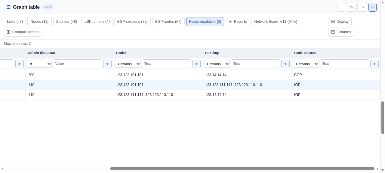
- Open Route resolution and read the result from left to right: the first row is BGP with administrative distance 200 and next hop 123.14.14.14 (PE14).
- Continue through the five IGP rows with administrative distance 110 that physically resolve reachability from 123.123.30.30 (PE30) to 123.14.14.14 (PE14).
The table below separates the single BGP route choice from the IGP hops that make its next hop reachable.
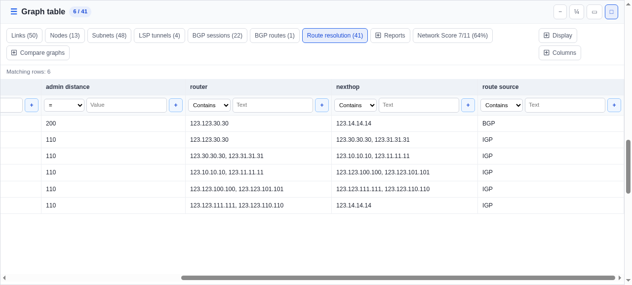
The BGP next hop points to 123.14.14.14 (PE14); the rest of the route is then built from OSPF data.
10. Unbuildable view
Filter for 123.123.31.31 (PE31). Topolograph can show the routes that 123.123.100.100 (RR1) received from 123.123.31.31 (PE31), but RFC 7854 alone does not reveal which route 123.123.31.31 (PE31) installed or what 123.123.100.100 (RR1) advertised back to it.
- Open BGP Routes and filter the peer ip column by 123.123.31.31. Adj-RIB-In (pre) and Adj-RIB-In (post) show routes that 123.123.100.100 (RR1) received from 123.123.31.31 (PE31), not 123.123.31.31 (PE31)'s routing table.
- Open the BGP / VPN path form and select Router 123.123.31.31. The form warns that this router's table is not observed and does not allow a path to be built from BGP data.
- Compare 123.123.31.31 (PE31) with 123.15.15.15 (PE15): for 123.15.15.15 (PE15), Topolograph uses 123.123.101.101 (RR2) Loc-RIB and explicitly assumes that 123.123.101.101 (RR2) advertised the route to 123.15.15.15 (PE15) and 123.15.15.15 (PE15) applied its inbound policy.
Topolograph does not build a path when the available BMP data does not describe the selected device's routing table. To remove this limit, provide the device's Loc-RIB through RFC 9069 or its per-neighbor Adj-RIB-Out post-policy through RFC 8671.
11. EVPN: where a host is, which leaves carry a VNI, MAC moves
The demo also holds a BGP EVPN/VXLAN fabric captured on the 13-hosts-demo-bgp lab: leaves 123.14.14.14, 123.15.15.15, 123.123.30.30 and 123.123.31.31, each using its router ID as VTEP, L2VNI 1010 on all four and L2VNI 1020 on 123.123.30.30 and 123.123.31.31, and VRF tenant1 with L3VNI 5000. Both route reflectors export it over BMP.
Which leaves carry a VNI
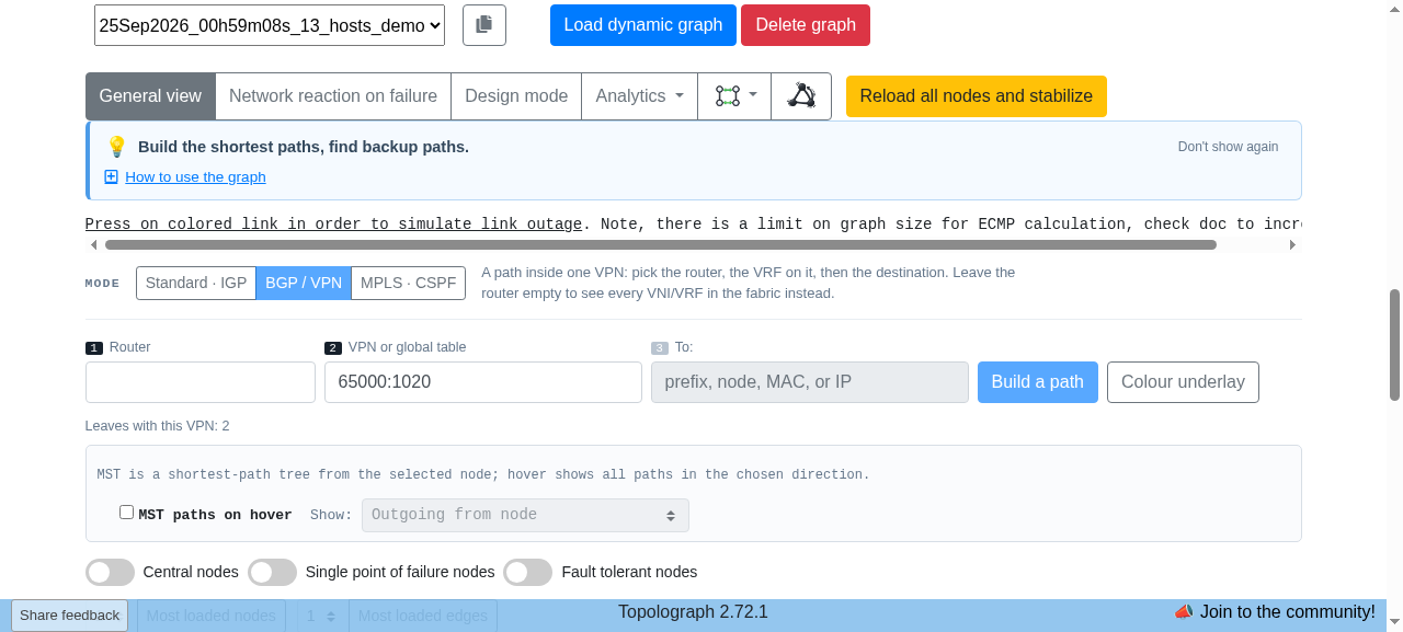
- Switch to BGP / VPN path mode and leave Router empty. VPN or global table then lists every VNI and VRF of the fabric.
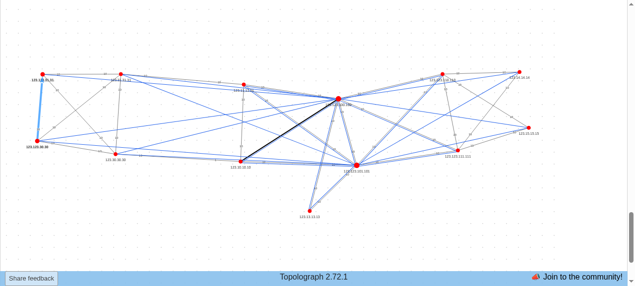
- Choose 65000:1020 · VNI 1020. The graph highlights 123.123.30.30 and 123.123.31.31, and the form reports Leaves with this VPN: 2.
- Press Colour underlay to paint the IGP path between these leaves: the links that carry VNI 1020 between its VTEPs.
EVPN on a leaf
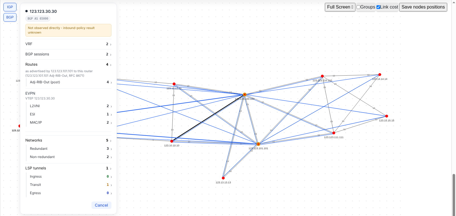
- Click 123.123.30.30 on the graph. The EVPN section of the device form shows its VTEP and three counts: L2VNI 2, ESI 1 and MAC/IP 2.
- The counts cover only what this VTEP originates, so the form stays short on a leaf with thousands of VNIs. ESI is hidden on a leaf without multihoming, as on 123.14.14.14.
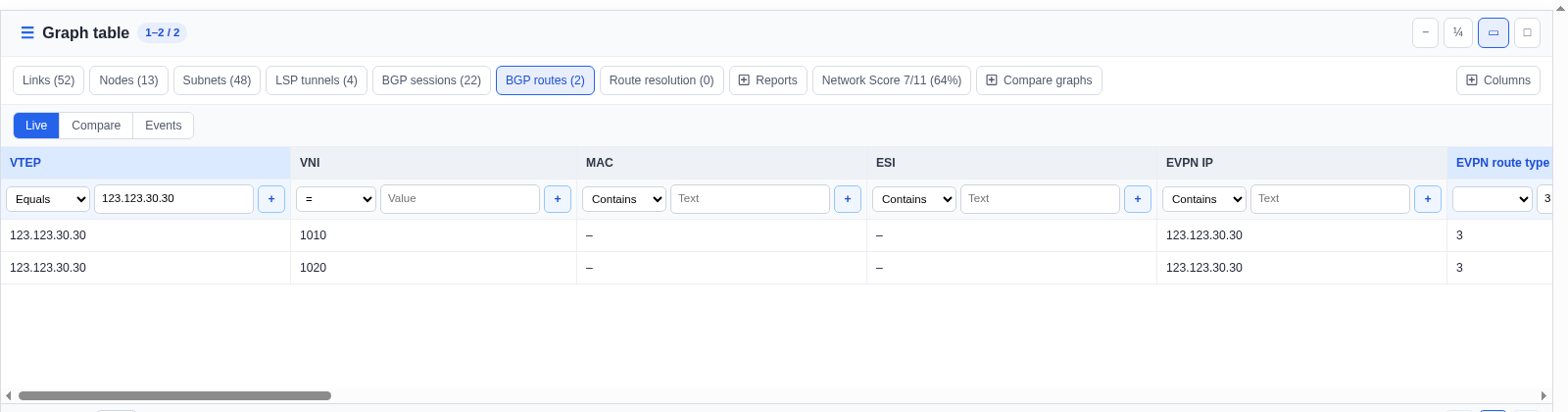
- Click L2VNI. Graph table opens BGP Routes with one row per VNI, 1010 and 1020, filtered by the leaf's VTEP. ESI and MAC/IP open its Ethernet Segments and hosts the same way.
Where a host is
- Set Router to 123.15.15.15 and VPN or global table to tenant1.
- Type 10.10.20.13 into To. Graph table opens BGP Routes with the host's row: VTEP 123.123.31.31, VNI 1020, L3VNI 5000 and MAC 00:c1:ab:00:00:03.
- Press Build a path. The IGP path from 123.15.15.15 to VTEP 123.123.31.31 is painted: the host exists only in the overlay, so the path ends at its VTEP.
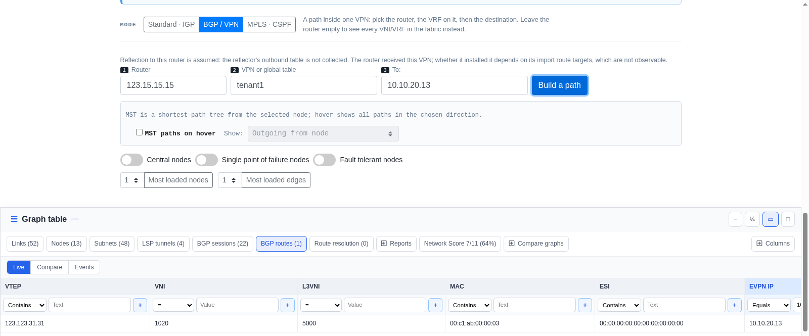
123.15.15.15 carries VNI 1010 but not VNI 1020, so it reaches this host through VRF tenant1 (symmetric IRB, L3VNI 5000), not through the VNI.
Did a MAC move
- Set Router to 123.123.101.101 and VPN or global table to 65000:1010 · VNI 1010.
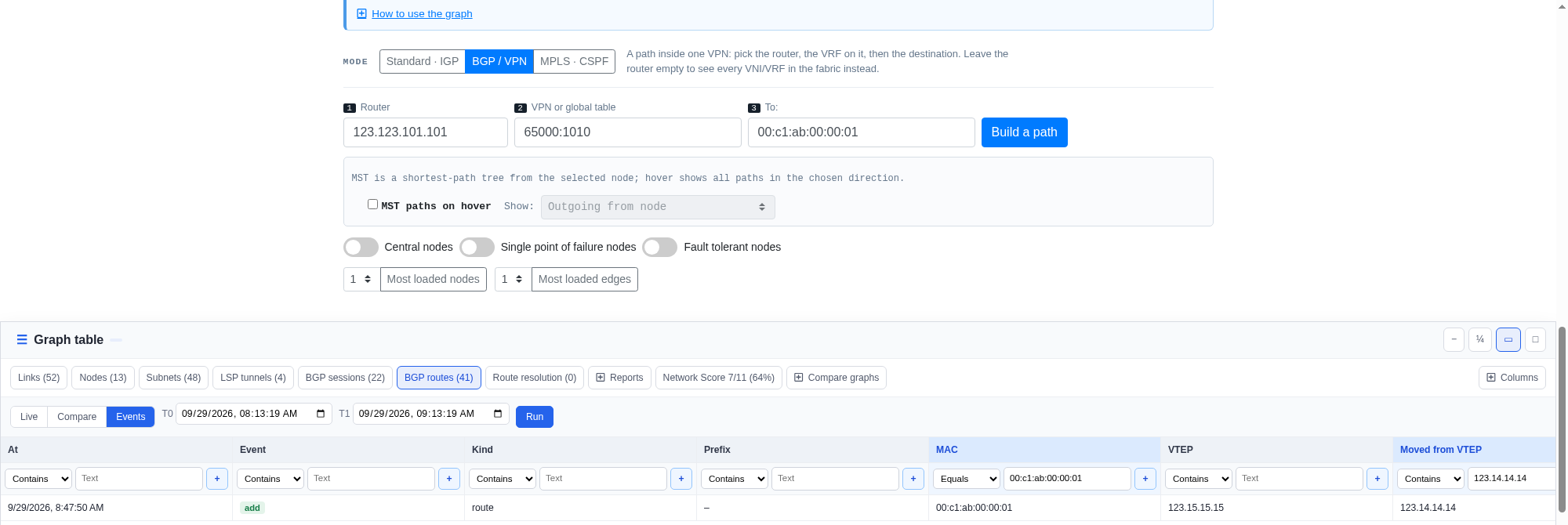
- Type the MAC 00:c1:ab:00:00:01 into To. Graph table shows its current VTEP 123.15.15.15. Switch the table to Events and press Run, then type 123.14.14.14 into the Moved from VTEP filter: the remaining row is the move itself, the add on 123.15.15.15 with its time.
- A move is the MAC leaving one VTEP and appearing on another. The same MAC advertised by several VTEPs under one ESI is multihoming, not a move.
A multihomed host
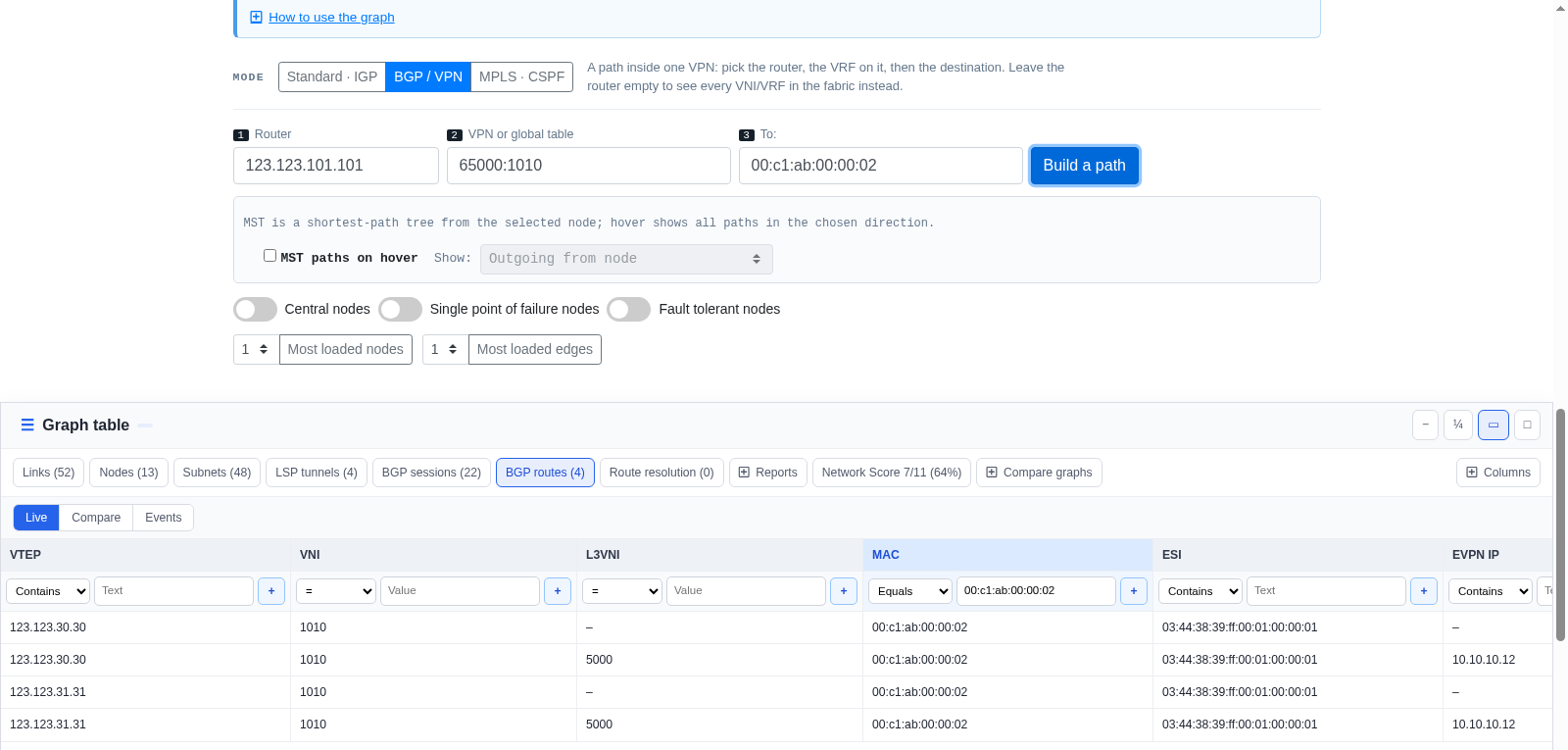
- Keep Router 123.123.101.101 and VNI 1010, and type 00:c1:ab:00:00:02 into To.
- Graph table lists the MAC on two VTEPs, 123.123.30.30 and 123.123.31.31, with one ESI 03:44:38:39:ff:00:01:00:00:01: the host is attached to both leaves through one Ethernet Segment.
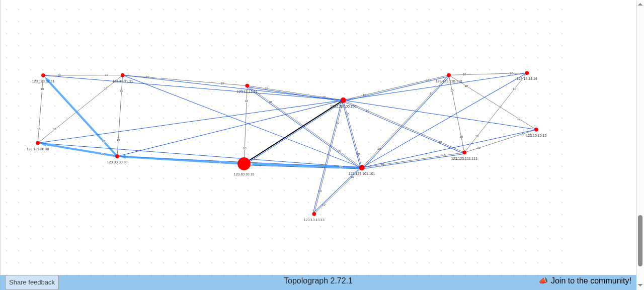
- Press Build a path. The paths to both VTEPs are painted at once. If one leaf fails, the other still serves the segment; which leaf forwards broadcast traffic (the designated forwarder) is decided on the leaves and is not visible over BMP.
Subnets of a VRF
- Open Graph table, select BGP Routes and filter evpn route type by 5.
- The table lists the IP Prefix routes of VRF tenant1: 10.10.10.0/24 from all four leaves and 10.10.20.0/24 from 123.123.30.30 and 123.123.31.31, each with L3VNI 5000 and its leaf as the VTEP.
Every answer comes from the BMP feed of the route reflectors, resolved onto the OSPF graph: a VTEP is the leaf with that router ID, and a path to a host ends at its VTEP.