OSPF Commands
| Vendor | LSA1 | LSA2 | LSA5 | NAPALM support |
|---|---|---|---|---|
| Cisco | show ip ospf database router | show ip ospf database network | show ip ospf database external | YES |
| Cisco NX-OS | show ip ospf database router detail | show ip ospf database network detail | show ip ospf database external detail | NO |
| Fortinet | get router info ospf database router lsa | get router info ospf database network lsa | get router info ospf database external lsa | NO |
| FRR/Quagga | show ip ospf database router | show ip ospf database network | show ip ospf database external | YES |
| Ruckus | show ip ospf database link-state router | show ip ospf database link-state network | show ip ospf database external-link-state | No |
| Juniper | show ospf database router extensive | no-more | show ospf database network extensive | no-more | show ospf database external extensive | no-more | YES |
| Bird | show ospf state all | show ospf state all | show ospf state all | NO |
| Nokia | show router ospf database type router detail | show router ospf database type network detail | show router ospf database type external detail | YES |
| Mikrotik | /routing ospf lsa print detail file=lsa.txt | /routing ospf lsa print detail file=lsa.txt | /routing ospf lsa print detail file=lsa.txt | No |
| Huawei | display ospf lsdb router | display ospf lsdb network | display ospf lsdb ase | No |
| Paloalto | show routing protocol ospf dumplsdb | show routing protocol ospf dumplsdb | show routing protocol ospf dumplsdb | No |
| No | ||||
| Ubiquiti | show ip ospf database router | show ip ospf database network | show ip ospf database external | No |
| Allied Telesis | show ip ospf database router | show ip ospf database network | show ip ospf database external | No |
| Extreme | show ospf lsdb detail lstype router | show ospf lsdb detail lstype network | show ospf lsdb detail lstype as-external | No |
| Ericsson | show ospf database router detail | show ospf database network detail | show ospf database external detail | No |
| Mandatory | YES | YES | NO |
OSPFv3 commands
OSPFv3 (RFC 5340) LSDB topology visualization. Save the output from the command into a file with .txt or .log extenstion and upload it to Topolograph.
| Vendor | Command | API support |
|---|---|---|
| Arista | show ipv6 ospf database detail | YES |
Save the output from min two OSPF commands (for getting LSA1 and LSA2 ) or single IS-IS command and upload it to Topolograph with .txt or .log extenstion.
IS-IS Commands
| Vendor | Command | API support |
|---|---|---|
| Cisco | show isis database detail | YES |
| Juniper | show isis database extensive | YES |
| Nokia | show router isis database detail | YES |
| Huawei | display isis lsdb verbose | YES |
| FRR | show isis database detail* (router-isis#no hostname dynamic) | YES |
*FRR mixes LSPIDs and dynamic hostnames in IS-IS LSDB, that's why building IS-IS topology without hostnames is supported only. "no hostname dynamic" disable dynamic hostnames in local IS-IS LSDB.
IS-IS TLV support
| TLV name | TLV number | Cisco | Juniper | Nokia | FRR | Huawei | ZTE |
|---|---|---|---|---|---|---|---|
| IS Reachability | 2 | YES | YES | YES | YES | YES | |
| Extended IS Reachability (new) | 22 | YES | YES | YES | YES | YES | YES |
| IPv4 Internal Reachability (old) | 128 | YES | YES | YES | YES | YES | |
| IPv4 External Reachability (old) | 130 | ||||||
| Extended IPv4 Reachability (new) | 135 | YES | YES | YES | YES | YES | YES |
| IPv6 Reachability | 2 | YES | YES | YES | YES | YES | YES |
GeneralView
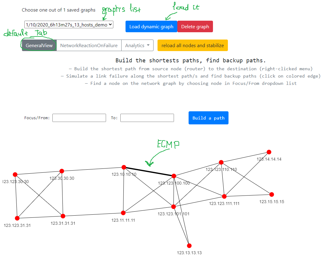
Demo network has already uploaded for everyone. Press `Load dynamic graph` in order to upload it. Once you did it - you can see the topology, bold lines show ECMP links.
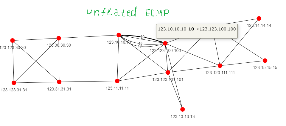
Press on bold line in order to unflat ECMP and see all nested links.
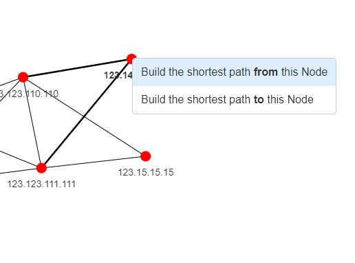
The shortest path. How to build.
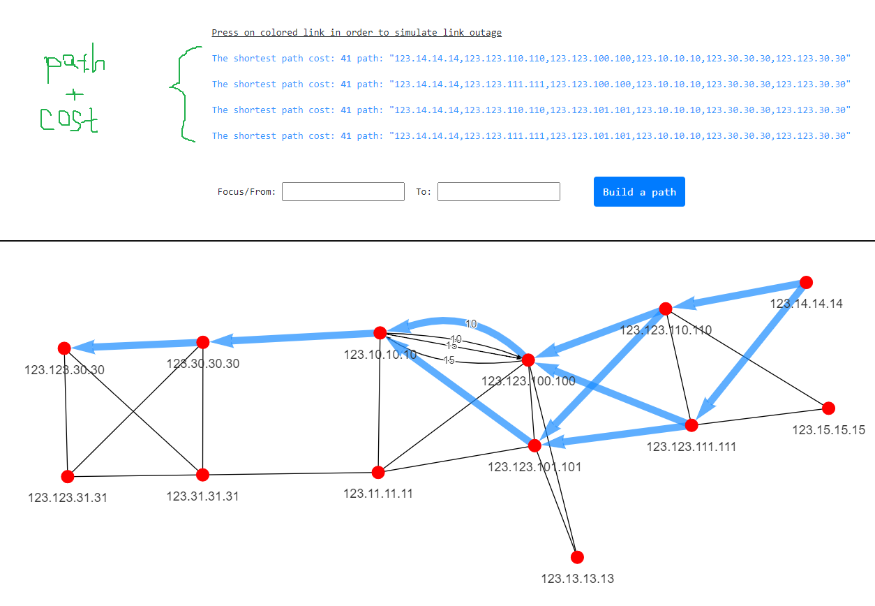
It's possible to build the shortest path from a node. Just right click on a node. The description with all nodes and path cost is available above the topology.
Once you set the source and destination - you get colored the shortest path.
All the shortest paths to all nodes. Minimum Shortest Tree.
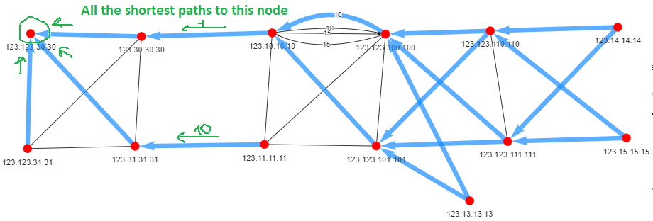
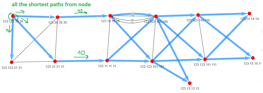
New feature of v2.11 release. MST allows see all the shortest paths To or From node. Just activate it from this radio-checkbox.
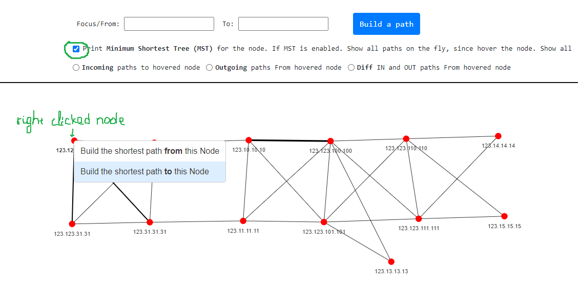
New feature of v2.11 release. All incoming the shortest paths are built to the node.
New feature of v2.11 release. All outgoing the shortest paths are built from the node.
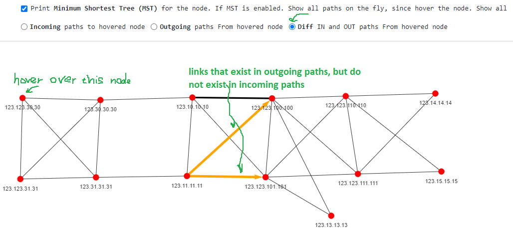
New feature of v2.13 release. Difference between incoming and outgoing the shortest paths of selected node.
Network's termination device search
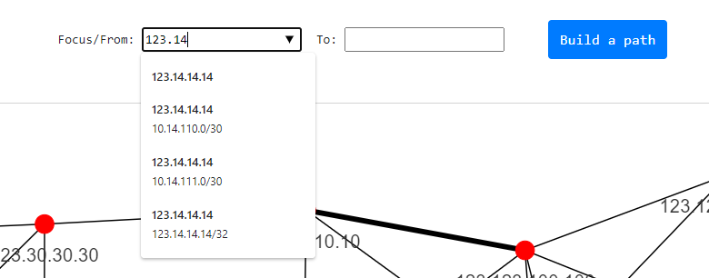
How is it possible to know what networks are terminated on some particular node. Thera are two ways how to know about it. The first one - start typing Node ID in "Find node by RID/IP. Find network" field and you will see all terminated networks on the node.
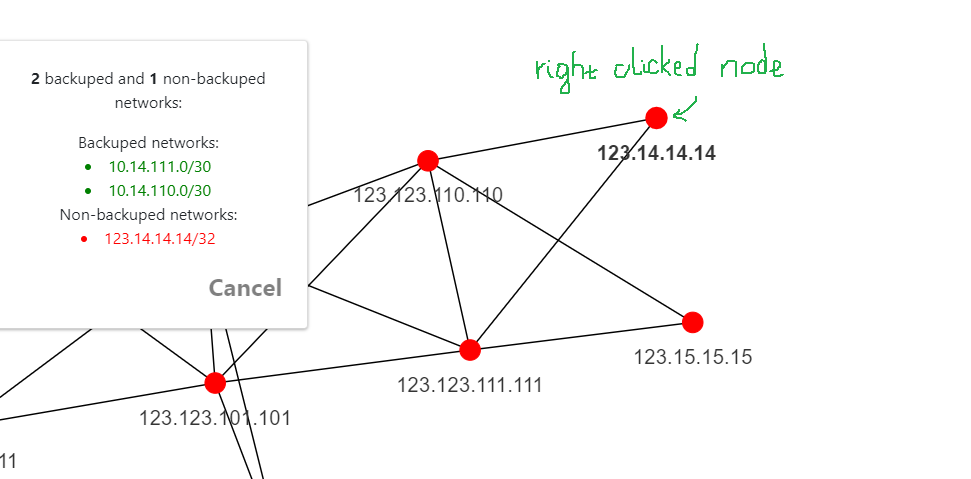
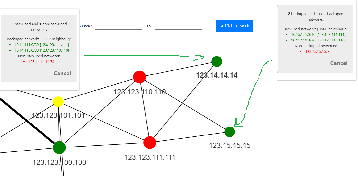
The second method is just to press on a node. New form pops up with a list of all backuped and non-backuped networks. The network is trated as backuped if such network is terminated on min two nodes.
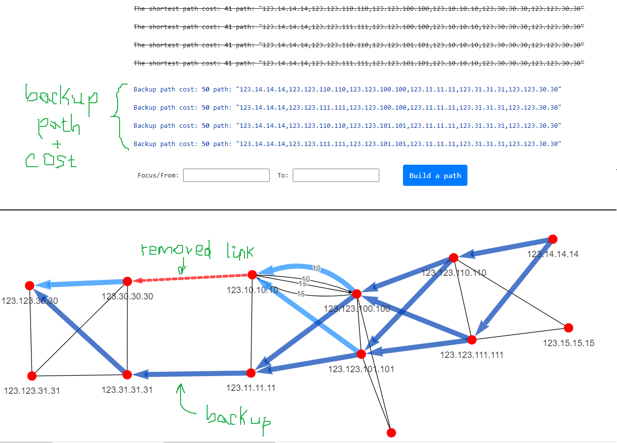
Backup paths. Link outage emulation.
In order to find out the backup path - just press on colored edge. You will simulate a link outage and the shortest path will be rebuilt passing by a 'failed" edge.
Shortest path rebuilding by changing ospf cost on the fly
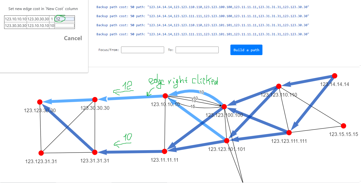
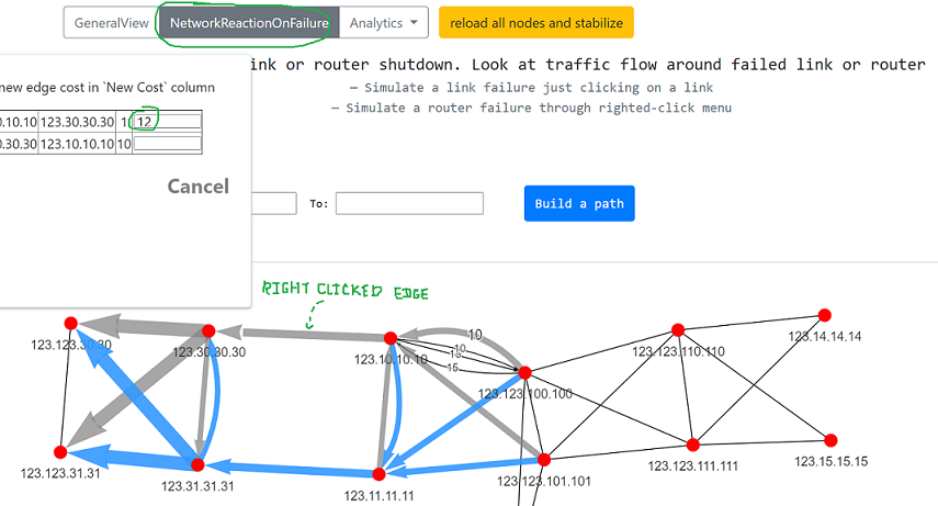
It's possible to change OSPF cost of any link. Right click on edge, new form pops up. Write new ospf cost in input field. Imagine if we need to redirect a traffic flow from 123.10.10.10 - 123.30.30.30 link to another link.
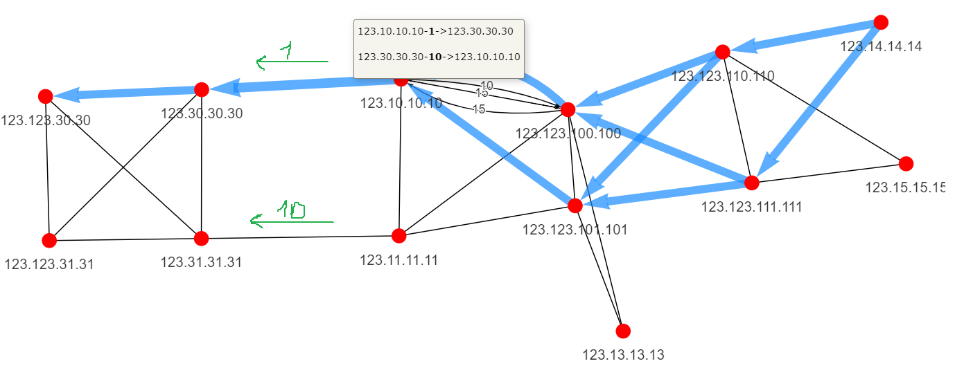
Right click on colored edge and set 12. We get new traffic flow with new OSPF cost.
Compare state of your network in different time
When you perform some configuration changes (add new network, redistribute another protocol to OSPF or change filters in existed route-maps) it is highly desire to make sure that results of you action give you expected changes in OSPF network. In order to do this - upload your network before your changes and right after it and compare them. What will be shown:
- New/old nodes
- New/old networks
- Links with new/old ospf cost

NetworkReactionOnFailure
In this mode it's possible to simulate a link or router shutdown/outage. The topology will be re-pained with expected changed traffic flow avoiding failed link or router.
Network reaction if a link/s goes down. Simulate link down.
Upload a graph if did't do it before and press on NetworkReactionOnFailure.
- Blue lines show traffic increasing over the link
- Grey lines show traffic decreasing over the link
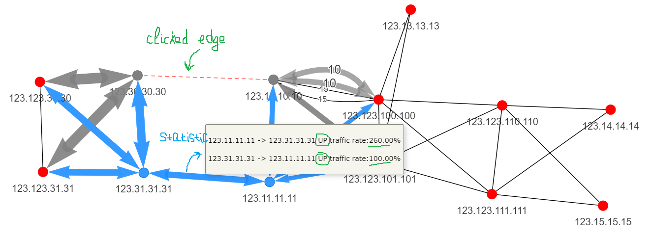
As you can see decreasing rate of traffic from 123.30.30.30 node to 123.123.30.30 and 123.123.31.31 differ from opposite direction [ from 123.123.30.30 to 123.30.30.30 ] upto ~2times. It happens because of the unsymmetric traffic path.
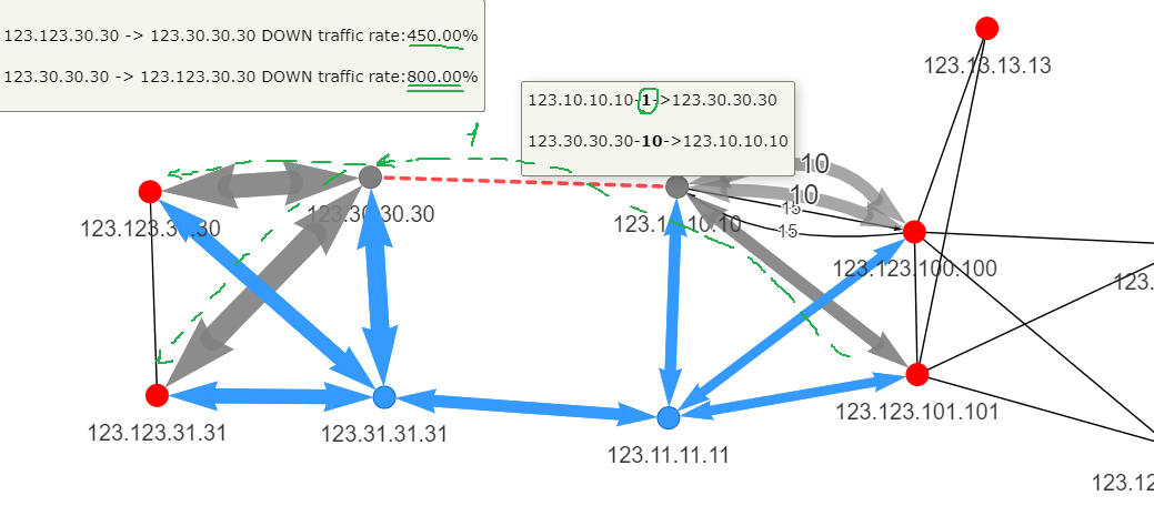
We also can see an expected increasing rate of blue painted edge.

Network reaction if a link/s goes down on shared media.
Topolograph builds a topology based on OSPF adjacency and physical connectivity is hidden. But in some cases, we can assume that neighbors share the same media, in some cases - not. For example, if neighbors have a common DR - we assume that they are connected via shared physical media and then we emulate one of the edge failures between such neighbors - we emulate all edges down.
Mark all shared media links (which have common DR) as enabled
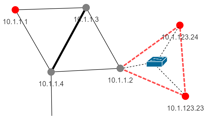
Network reaction if a link/s goes down on dedicated media.
If neighbors do not have DR or they have, but they are only two neighbors on the link, and when we emulate edge failure - we remove the only a single link between two particular neighbors.
Mark all shared media links (which have common DR) as disabled
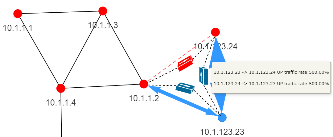
Network reaction if a network devices goes down. Simulate device down.
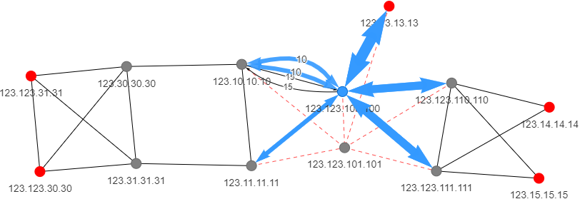
Right click on a node and choose `shutdown this node`. The algorithm escape this node.
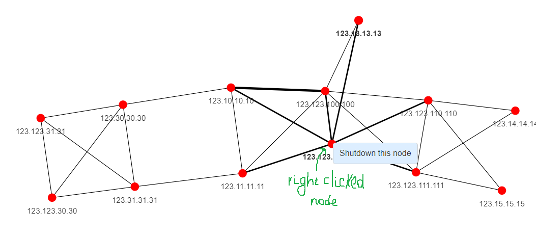
The network reaction on 123.123.101.101 node outage.
Network reaction on OSPF link cost changes.
Under NetworkReactionOnFailure tab it is possible to see a network reaction on a OSPF cost change on the fly. Set new OSPF cost in righted-clicked edge menu.
Network Design Mode
OSPF/IS-IS LSDB <-> YAML is interchangable now in both ways, so it allows to make a design of IGP domain from the scratch or based on uploaded a LSDB, add new links/edges between nodes or change igp's cost and then check network reaction based on our changes.
Basic YAML based topology.
Build a graph with defined nodes and edges.
Node attributes
node's name is mandatory. Should be in IP-address format. To change it to any other value - use label
Tags of node are optional. Any key (type string): value (str, int, float, dictionary, list) pairs.
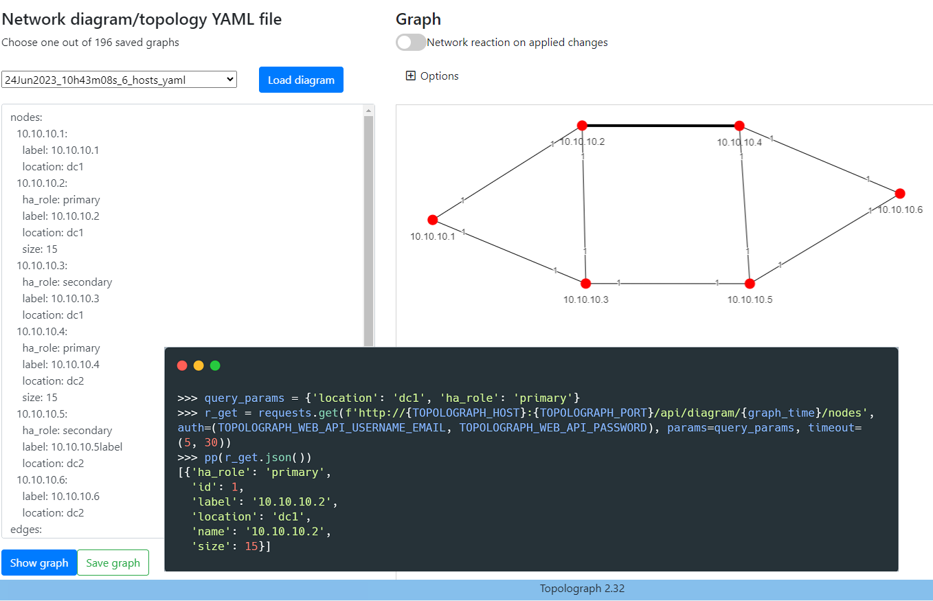
There is a graph with 6 nodes. Select all primary nodes (ha_role: primary) in the first DC (dc1)
Edge attributes
src, dst is mandatory.
cost is optional. Default is 1. Equal to OSPF/IS-IS cost.
directed is optional. Default is false.
Tags of edge are optional. Any key (type string): value (str, int, float, dictionary, list) pairs.
Select all edges over verizon ISP between 10.10.10.2 and 10.10.10.4
Network reaction on adding new link between devices.
Let's add a new link with cost 1 between R3 (10.10.10.3) and R4 (10.10.10.4) device and see how network will react on it.
Obviously, we see traffic increase on direct link R3<->R4 and traffic decrease to R2 (10.10.10.2) and R5 (10.10.10.5).
Analytics
In this mode it's possible to run algorithms in order to check your OSPF network.
Unidirectional and asymmetric links.
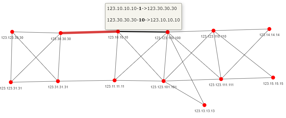
Print out any Unidirectional links ( number of IN and OUT links between two neighbors is not equal)

The edge is marked as red edge because of cost 1 and cost 10 OSPF metric
Asymmetric paths.
Print out any asymmetric paths from different points of views.

We get a list of nodes which have asymmetric paths. Just checking them - we can see difference in incoming and Outgoing paths.

Main and backup paths via the same ECMP.
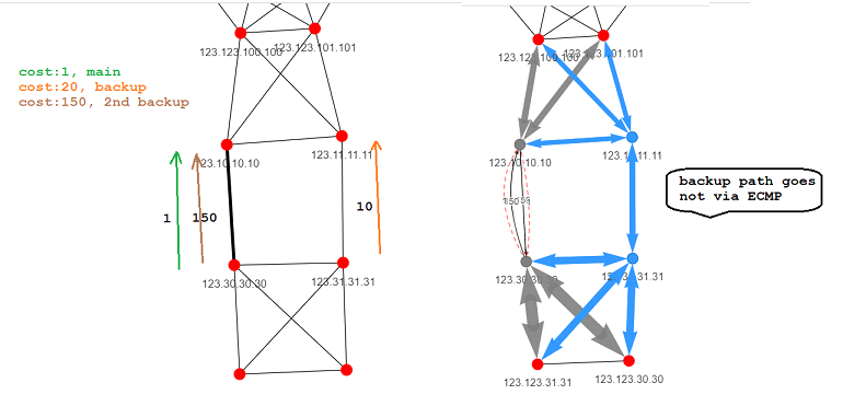
We suggest that if we have multiple links bounded to ECMP and if the main link in ECMP goes down, the backup path should go via the second link in ECMP.
Passed report
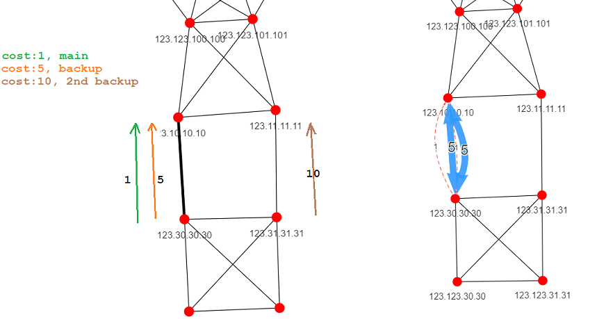
If backup path goes not via ECMP and chooses completely different path - the report will be treated as failed.
Failed report
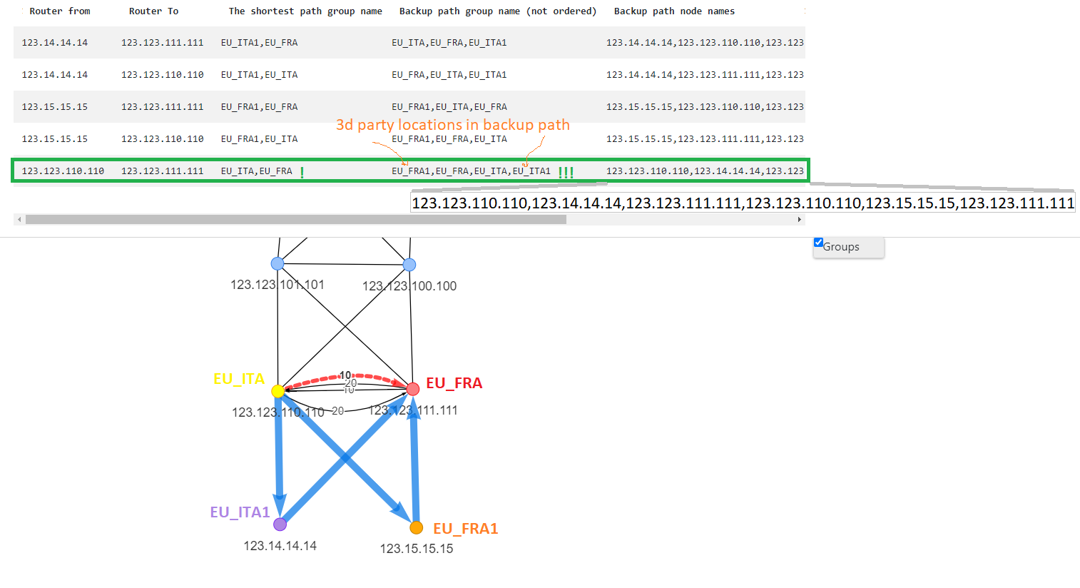
Backup paths via 3d party locations.
This report checks that if two locations are directly connected, backup paths should be only between two locations and do not go via third location as transit. Before running this report - it's needed to create groups (~site names/locations) and assign devices to groups. For example, there are two locations in France: the main site (EU_FRA) and the remote site (EU_FRA1). The same schema with offices in Italy. The main offices in France and Italy are connected to each other and have main (OSPF cost 10) and backup (OSPF cost 20) link.
Remote offices have the main link (OSPF cost 1) to their main offices and backup link (OSPF cost 10) to the foreign office.
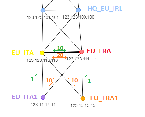
Failed report
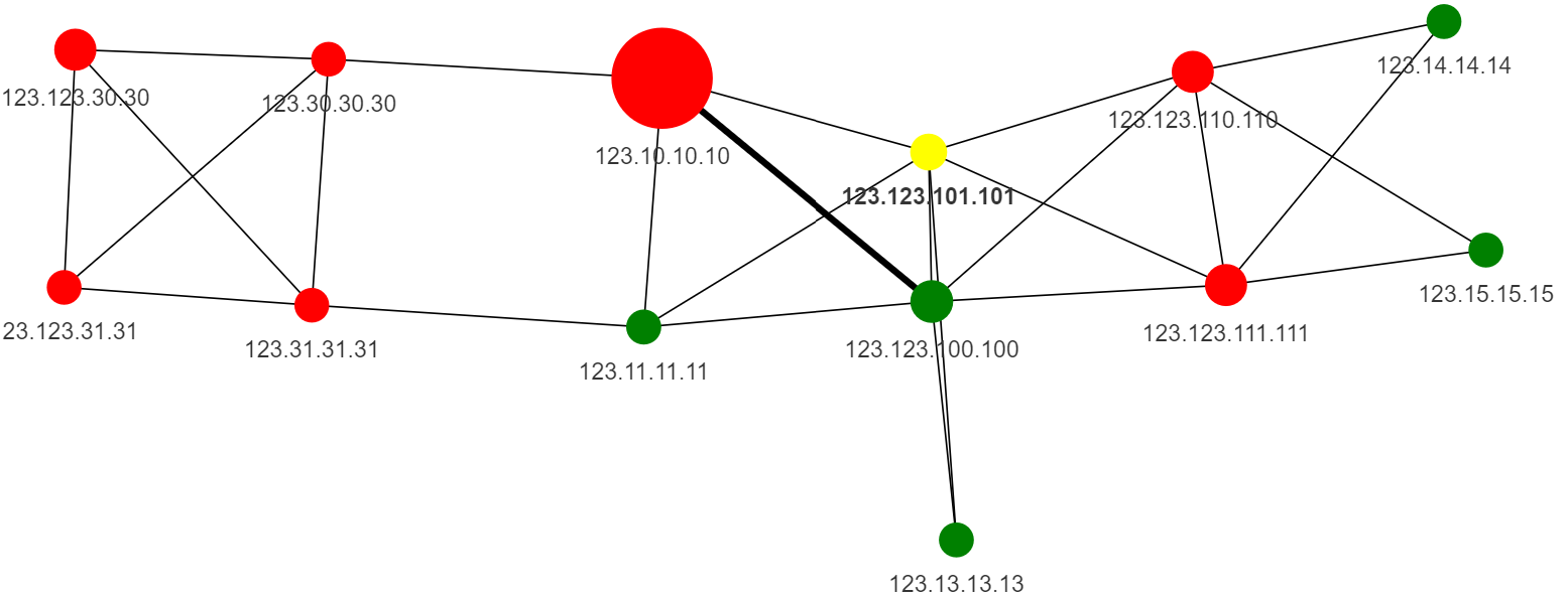
Network heatmap
Under Analytics tab it is possible to see how many terminated subnets are backuped via terminating the same subnet on different devices.
Click on a node in order to find out which networks are backuped which not.
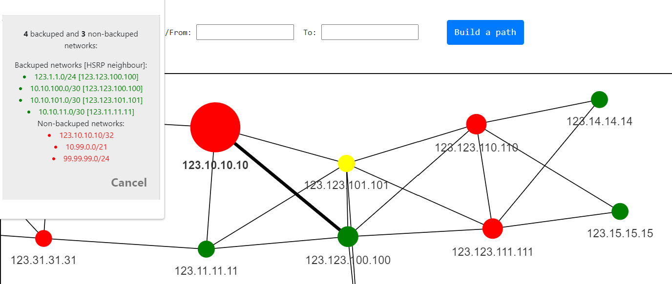
As we can see only own device's loopback is not backuped - it is normal.
Duplicated networks [MPLS]
"Analytics/Duplicated terminated networks. The issue with MPLS being affected by IP duplications in the network stems from the fact that labels are generated based on IP blocks, which can be duplicated. As a result, the same IP block may be associated with different labels. This leads to a situation where the same block, with different labels, is propagated to other routers, including the one with the duplicated IP. This becomes problematic when implementing MPLS Traffic Engineering (MPLS-TE) or Resource Reservation Protocol Traffic Engineering (RSVP-TE), as it can degrade performance and lead to routing bugs in relation to MPLS-TE, among other issues. Therefore, the issue of block duplication across links is critical in MPLS environments, primarily due to the generation of duplicate labels for the same block. In routers, this causes confusion when recalculating the path for TE or RSVP-TE."
| Network | Number of terminated nodes | Node names |
|---|---|---|
| 10.0.0.0/24 | 4 | [172.16.1.2, 172.26.1.2], [172.30.2.1, 178.20.3.1] |
10.0.0.0/24 network is terminated on four nodes: 172.16.1.2, 172.26.1.2 and 172.30.2.1, 178.20.3.1 are directly connected, but not between each other.
API
It's time not to depends on NAPALM support of the vendor. You are free to choose your favorite NetDevOps tool like Ansible, netmiko, Nornir, etc, and upload your OSPF network graph to Topolograph via a POST request. Once you uploaded the graph - you get the difference with previously uploaded graphs, specifically, you will receive: new/old OSPF adjacencies (edges on the graph) new/old devices in OSPF topology number of backuped and non backuped subnets in the topology
Get credentials.
It's needed to create an account with email/password on Login/Registration page as well as add your source IP/Network to authorised source network list under API tab.
Upload OSPF topology via API
Save the output from commands describing OSPF LSA1, LSA2, LSA2 and save it in the single file - cisco_lsdb_output.txt
      import requests
      from pprint import pprint as pp
      with open('cisco_lsdb_output.txt') as f:
        lsdb_output = f.read()
        r_post = requests.post('https://topolograph.com/api/graph', auth=('youraccount@domain.com', 'your-pass'),
                                json={'lsdb_output': lsdb_output, 'vendor_device': 'Cisco'})
        pp(r_post.json())
Using python we read the content of the file and push it (it's better to say - POST it) to the topolograph.
The output returns:
        >>> pp(r_post.json())
        {'diff': {'compared_with_graph_time': '02Jun2021_21h18m04s_13_hosts',
                  'graphs_diff': {'all_edges_stats_ll': [{'dst_node': '123.123.110.110',
                                                          'link_cost': 10,
                                                          'link_status': 'old',
                                                          'src_node': '123.123.100.100'},
                                                         {'dst_node': '123.123.111.111',
                                                          'link_cost': 10,
                                                          'link_status': 'old',
                                                          'src_node': '123.123.101.101'},
                                                         {'dst_node': '123.123.100.100',
                                                          'link_cost': 10,
                                                          'link_status': 'old',
                                                          'src_node': '123.123.110.110'},
                                                         {'dst_node': '123.123.101.101',
                                                          'link_cost': 10,
                                                          'link_status': 'old',
                                                          'src_node': '123.123.111.111'}],
                                  'new_nodes': [],
                                  'old_nodes': []},
                  'networks_diff': {'new_subnets_attr_dd_ll': [{'rid': '123.30.30.30',
                                                                'subnet': '30.30.30.30/32'}],
                                    'old_subnets_attr_dd_ll': [{'rid': '123.10.10.10',
                                                                'subnet': '1.2.3.0/30'}]}},
        'graph_time': '08Jun2021_20h15m26s_13_hosts',
        'hosts': {'count': 12},
        'networks': {'backuped': 14,
                      'count': 38,
                      'notbackuped': 24,
                      'url_link': 'https://topolograph.com/api/network/08Jun2021_20h15m26s_13_hosts'},
        'reports': {'asym_edges_pass_status': False},
        'timestamp': '2021-06-8T20:15:26.265000'}
Visual difference between OSPF states.

        >>> pp(r_post.json())
        {'diff': {'compared_with_graph_time': '02Jun2021_21h18m04s_13_hosts',
                  'graphs_diff': {'all_edges_stats_ll': [{'dst_node': '123.123.110.110',
                                                          'link_cost': 10,
                                                          'link_status': 'old',
                                                          'src_node': '123.123.100.100'},
                                                         {'dst_node': '123.123.111.111',
                                                          'link_cost': 10,
                                                          'link_status': 'old',
                                                          'src_node': '123.123.101.101'},
                                                         {'dst_node': '123.123.100.100',
                                                          'link_cost': 10,
                                                          'link_status': 'old',
                                                          'src_node': '123.123.110.110'},
                                                         {'dst_node': '123.123.101.101',
                                                          'link_cost': 10,
                                                          'link_status': 'old',
                                                          'src_node': '123.123.111.111'}],
                                  'new_nodes': [],
                                  'old_nodes': []},
                  'networks_diff': {'new_subnets_attr_dd_ll': [{'rid': '123.30.30.30',
                                                                'subnet': '30.30.30.30/32'}],
                                    'old_subnets_attr_dd_ll': [{'rid': '123.10.10.10',
                                                                'subnet': '1.2.3.0/30'}]}},
        'graph_time': '08Jun2021_20h15m26s_13_hosts',
        'hosts': {'count': 12},
        'networks': {'backuped': 14,
                      'count': 38,
                      'notbackuped': 24,
                      'url_link': 'https://topolograph.com/api/network/08Jun2021_20h15m26s_13_hosts'},
        'reports': {'asym_edges_pass_status': False},
        'timestamp': '2021-06-8T20:15:26.265000'}
Upload Multiple OSPF LSDBs via API
Topology is built based on LSA1, LSA2, which are area only based. If a network has multiple areas, it is needed to save LSDB output from multiple devices and save it into separate files using the following format Vendor name_protocol name.txt
For instance: there are two LSDBs Cisco_ospf.txt, Juniper_ospf.txt
LSDBs are saved in lsdb_samples folder, then wrapped into LSDB attribute dictionary
{'lsdb_output': '...lsdb output...', 'vendor_device': 'Cisco, Juniper...', 'igp_protocol': 'ospf|isis'}
The full example:
      import requests
      TOPOLOGRAPH_HOST="127.0.0.1"
      TOPOLOGRAPH_PORT=5000
      TOPOLOGRAPH_WEB_API_USERNAME_EMAIL="your login"
      TOPOLOGRAPH_WEB_API_PASSWORD="your password"
      from pprint import pprint as pp

      lsdbs_attr_ll = []
      lsdb_dir = os.path.join(os.getcwd(), 'lsdb_samples')
      for vendor_name, protocol_name in [('Cisco', 'ospf'), ('Juniper', 'ospf')]:
        f_name = os.path.join(lsdb_dir, f"{vendor_name}_{protocol_name}.txt")
        with open(f_name) as f:
          lsdbs_attr_ll.append({'lsdb_output': f.read(), 'vendor_device': vendor_name, 'igp_protocol': protocol_name})
      r_post = requests.post(f'http://{TOPOLOGRAPH_HOST}:{TOPOLOGRAPH_PORT}/api/graphs', auth=(TOPOLOGRAPH_WEB_API_USERNAME_EMAIL, TOPOLOGRAPH_WEB_API_PASSWORD),  json=lsdbs_attr_ll, timeout=(5, 30))
      pp(r_post.json())
The output returns:
Groups & VRF
Multiple OSPF routing instances can exist on a single device in several VRFs. It causes nodes duplication on a visualisation graph. VRF tab allows to point multiple OSPF instances to a single one and avoid node duplication on a graph.
There are three VRFs and three OSPF instances on a router. In order to avoid node duplication - create VRFs (or import them via CSV), associate the node with VRF and point duplicated instances to master OSPF RID. the node with VRF and point duplicated instances to master OSPF RID.
